Giant robot arm
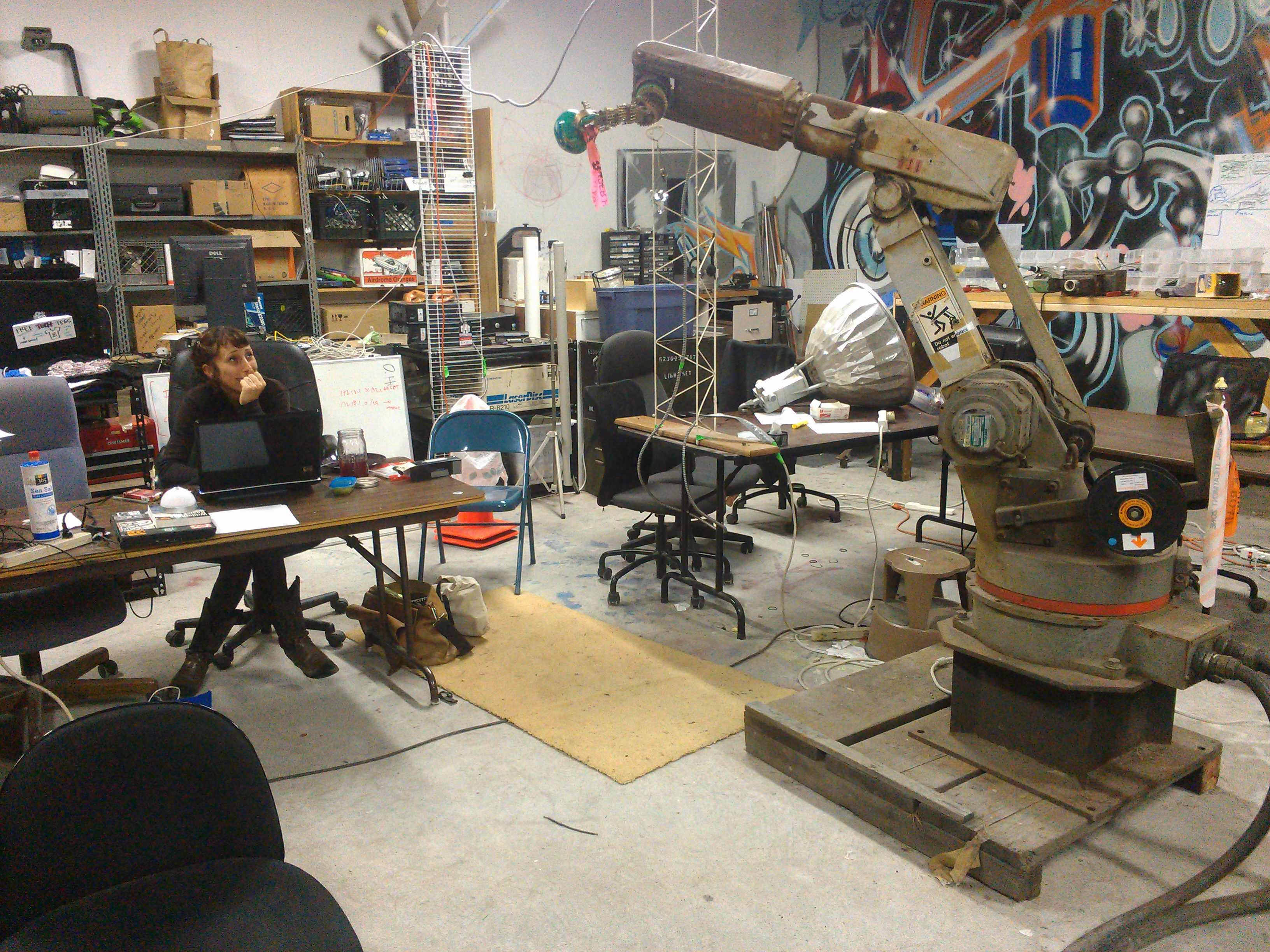
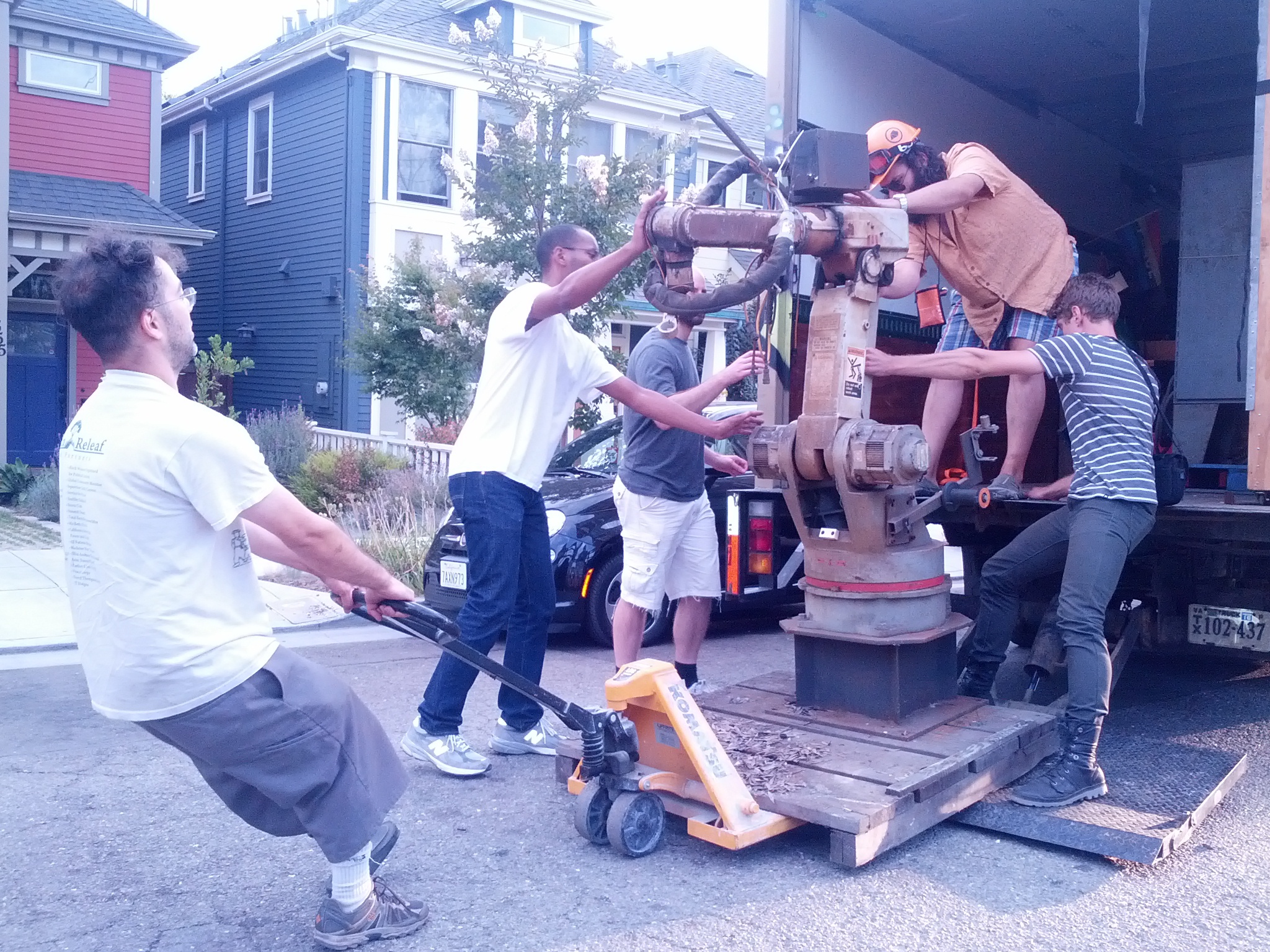
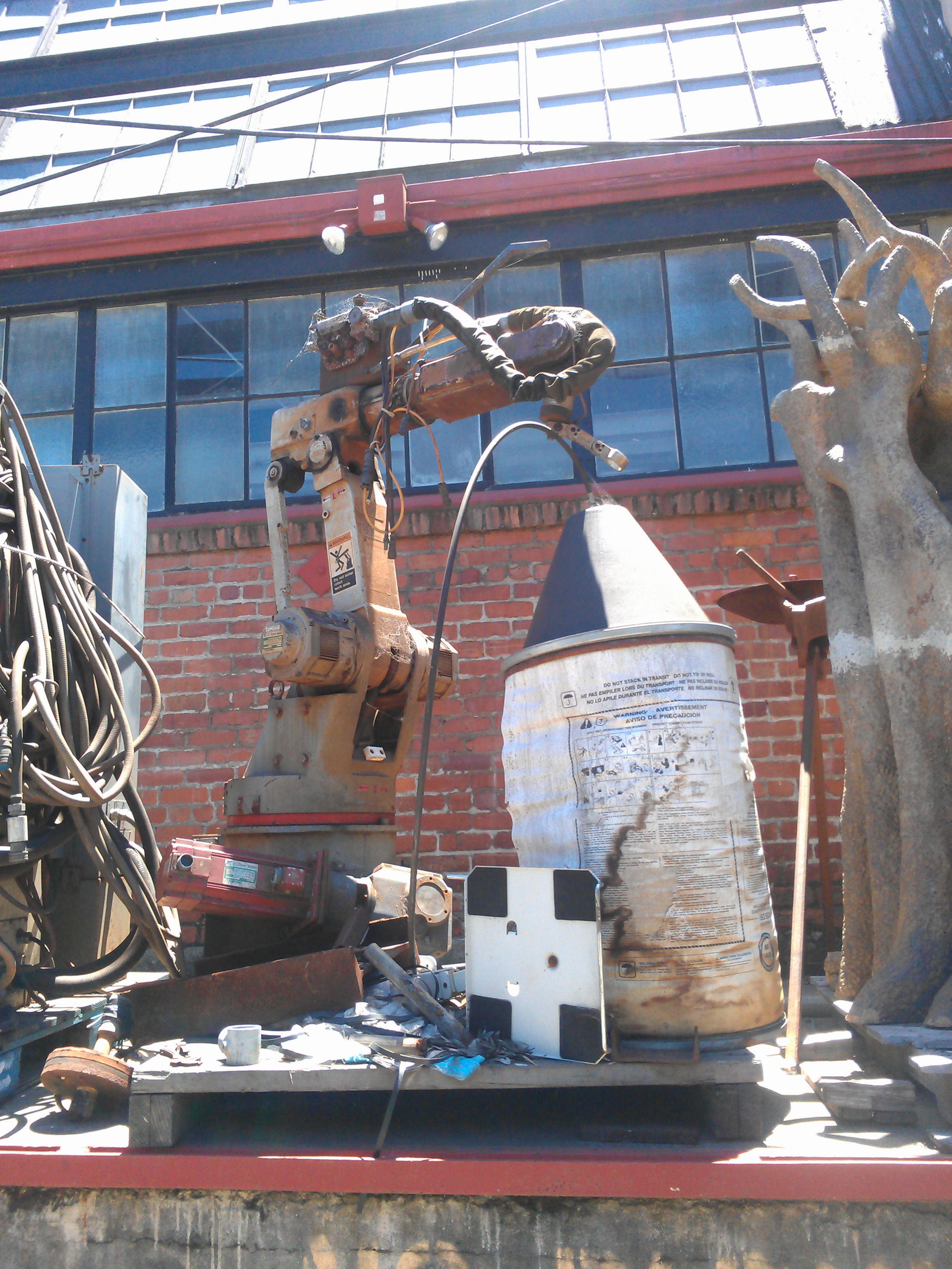
Yaskawa Motoman K10S
what is it for?
It's a six-axis CNC machine that is rated to move 10 kilograms around in any orientation, with 1mm accuracy.
software for communicating with the robot from a regular computer
https://github.com/jerkey/yasnac
Use motofile and motocommand while the REMOTE button on the robot is lit up. To enable the REMOTE button, you must enable remote operation first
Your computer must be connected to the robot over an RS232 serial cable. motofile lets you send job files to the robot, and motocommand lets you tell the robot what to do, as if you were pressing buttons on the control panels.
motomove can move the robot directly (without loading a job file) but it is poorly supported in the robot's firmware and was never considered complete by the manufacturer (they moved onto the MRC control system development for this) so use it with caution.
documentation
- Homing https://pdfcoffee.com/erc-homing-pdf-free.html
- Collection of docs http://spaz.org/~jake/robot
- INFORM Lanugage manual PDF and another copy here INFORM PDF
- Robotforum posts on the Yaskawa motoman k6sb with erc controller talk to these people for the conversation
enabling relative job function and the communications option
Ben says:
"If I remember, press OP2, enter the magic code 24.#4.#2 then set these:
set SD079 to 1 for relative job (x,y,z coordinates)
set SD110 to 1 for data communication (remote mode)
and reboot the robot."
Getting the robot working if it has forgotten its purpose
- There is a battery inside the connector compartment of the robot arm, and another next to the computer boards on the door of the control cabinet. If the batteries go dead or are disconnected, the robot will act stupid and refuse to boot up with some dumb error screen.
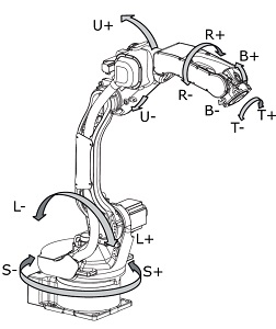
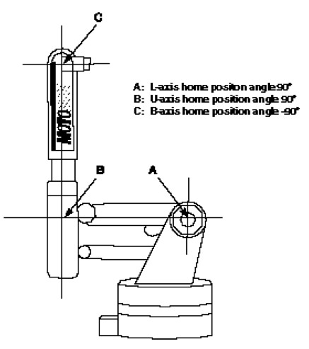
- Homing https://pdfcoffee.com/erc-homing-pdf-free.html basically, pose the robot as shown above, press OP2, press 0 eight times, ENTER, and then you can tell it that it's presently homed. You can also home fewer than all axes by selecting which axes you want to home, before pressing the button for "Setting" which is how you tell it to save the present position. As of 2022/12/7 the absolute encoder values for SLURBT are: 5771,30829,-25795,-792,66,-1047. IF the physical limit switch (for example on the S axis) is hit, you have to HOLD the "overrun" bypass button next to the serial port while booting up and CAREFULLY jogging S- or S+ to fix that problem, and then you can let go of the button.
- There is a switch inside the control cabinet on the edge of the CPU1 card which puts it into MAINT mode (switch up) or PARAM mode (switch down), normally the switch is in the middle. Hard-power cycling the robot is how you reboot it. picture of switch location close-up picture of switch
- Homing the robot is easy compared to getting the robot to be in the mood to be homed, especially after replacing the memory batteries. Don't be like this guy: https://www.robot-forum.com/robotforum/thread/14021-erc-k6sb-make-abs-data/ the PDF mentioned therein: MotomanERChomePosition.pdf
- after the robot is working, you will have to remind it that you paid for all the deluxe options, like rectangular coordinates and remote access serial stuff. The "magic code" is 24.#4.#2 and the instructions for entering it are above, recounted by Ben.
- If the robot wakes up to a MAKE ABS DATA error it's probably having trouble communicating with some of the position encoders on the motors. The ABSolute position encoders are backed up by a battery and they can get into a state where they don't work right, that's what's described in the previous links is to get them to cooperate.
The controller wants to see eight position encoders. Six motors of the robot, a 7th giant heavy motor/gearbox assembly on the floor, and an 8th simulated by an arduino hanging by the wires from the circuitboard inside the cabinet.We formerly used hardware to get it to boot up without errors, but moving jumpers on one of the circuit cards allowed it to be content with only the 6 axes of the arm itself.
Electrical components
- ACC-8D20 option PDF manual 33 page manual on ???
- encoder datasheet (pdf)(for different encoders?)
- Yaskawa CACR-SR Manual (PDF) <------- this is totally what we have, absolute encoders and CACR servopacks


Servo contactor wiring notes: coil 160 ohms, connector CN2 pins 2 and 6. CN2:6 is also on relay socket and CN5:7, assumed common. CN2:2 goes to CN5:8 and on to CN2CN:4 (near main on/off switch) where it gets jumped to CN2CN:3 by RLY12
Coordinate conversion and 3d model
Cool Projects
Drawing with the Robot Arm Project
Substack and Jake went ahead and hacked the robot (see the blog post ). now you can upload simple drawings and get it to draw for you.
- Get an image file (PNG) and convert it to SVG free convert to SVG web app
- Take the SVG and convert it to INFORM http://substack.neocities.org/svg2inform.html (thanks Substack!)
- Go to SudoRoom, chat with the right hackers, learn to calibrate (safety first!!!) and then let the robot do the drawing for you!
- Cheers! Cheers! More thanks to Jake for learning how to fake the serial disk https://github.com/jerkey/yasnac/blob/master/src/fakedisk.py
15:25 <@Rab> No small matter unfortunately, unless you get really imaginative on the CAM side and utilitize the robot's axes of movement in very simple ways. 15:27 <@Rab> I think it'll probably need to be somebody's brilliant custom CAM because open-sores CAM is pretty seriously limited, and more than 3-axis commercial CAM is insanely expensive. 15:28 <@Rab> PyCAM might be a start, that's what I'll use if I do anything 3D. 15:38 <@Rab> Autodesk Fusion 360 includes Autodesk's 3+2 CAM, which is probably the best and most usable CAM you'll find anywhere for zero dollars. But fuck that proprietary cloud shit. 15:42 <@Rab> CAM is one of those software applications which is so hard, anybody skilled enough to do it right also wants to get paid. That's a direct challenge to Sudo Room BTW. 15:45 <@Rab> You could join ##linuxcnc on feenode and see if anybody has any ideas.
Serial port pinout to connect to a regular PC (DTE) 9-pin socket
| DB25 pins | DE9 holes | Signal (DE9 end) | RJ45 pin# |
|---|---|---|---|
| 2 | 2 | RX | 2 |
| 3 | 3 | TX | 3 |
| 4 | 1 | DCD | 1 |
| 5 | 4 | DTR | 4 |
| 7 | 5 | GND | 5 |
