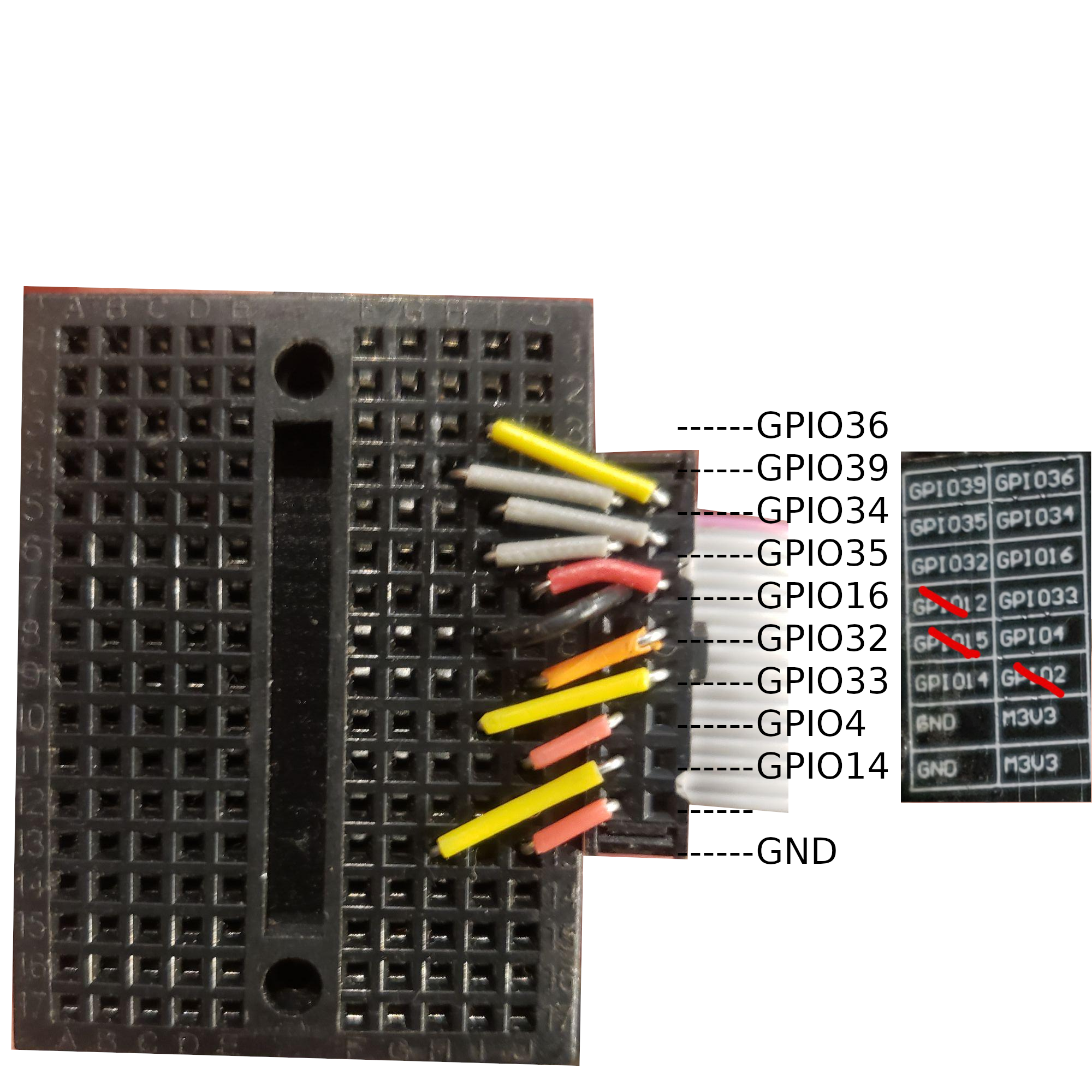
rules so that motor direction gets activated, with a timeout. But if current limit hits, then cancel
| Pin | thing | Mode in Tasmota Configure Unit menu |
| 4 | lock | Relay 1 |
| 32 | unlock | Relay 2 |
| 33 | current | ADC Current 1 |
| 36 | battery voltage | ADC Current 2 |
curl -u "admin:password" http://10.111/cm?cmnd=power1+1
Rule1 ON Power1#state=1 DO backlog Delay 50; Power1 0 ENDON
rule1 1
Rule2 ON Power2#state=1 DO backlog Delay 50; Power2 0 ENDON
rule2 1
Rule3 ON ANALOG#Voltage1>80 DO Power1 0; Power2 0 ENDON
rule3 1
(100 is too low, limit sometimes trips before motor starts moving, 200 is a lot)
set the adc range https://tasmota.github.io/docs/ADC/ (note: mode 6 is ADC Range, but 33 is what the software returns for some reason, so we just set 33)
AdcParam1 33, 0, 4095, 0, 100
AdcParam2 36, 0, 4095, 0, 3.3
in the console (or by curl) you can view the rules and adcparam
CMD: rule1
RSL: RESULT = {"Rule1":{"State":"ON","Once":"OFF","StopOnError":"OFF","Length":54,"Free":457,"Rules":"ON Power1#state=1 DO backlog Delay 100; Power1 0 ENDON"}}
CMD: rule3
RSL: RESULT = {"Rule3":{"State":"ON","Once":"OFF","StopOnError":"OFF","Length":40,"Free":471,"Rules":"ON ANALOG#Voltage1>80 DO Power1 0 ENDON"}}
CMD: adcparam
RSL: RESULT = {"AdcParam1":[33,0,4095,0,100]}
"The ESP32 board has four ADC GPIO pins available (gpio34, gpio35, gpio36, gpio39) which can be used for analog inputs. These can be used to read voltage at the ADC pin or to read the module supply voltage (VCC). All analog input pins support 3.3V."
