Difference between revisions of "Mesh/Meraki Sparky Enclosure Design"
Jump to navigation
Jump to search
| Line 3: | Line 3: | ||
notes about an enclosure for the Maraki Sparky | notes about an enclosure for the Maraki Sparky | ||
== first pass == | |||
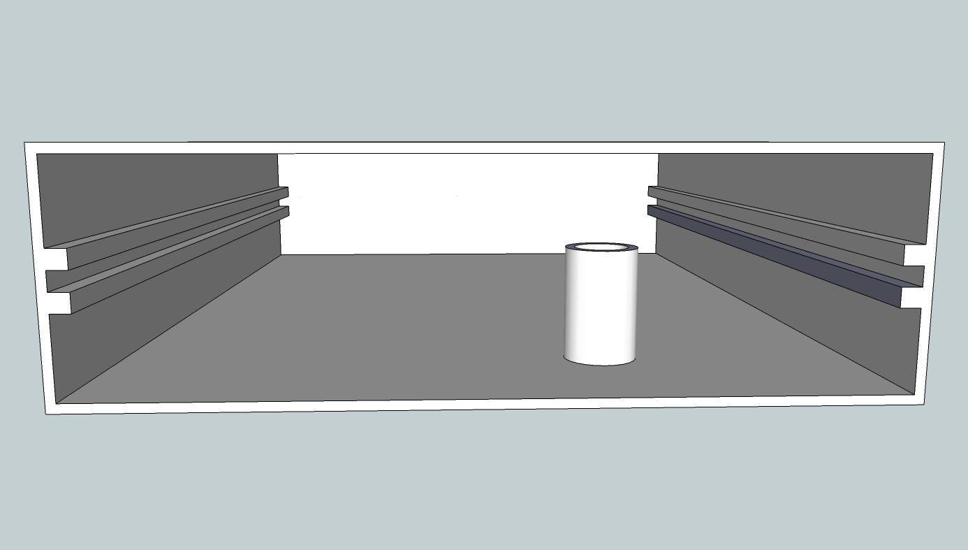
[[File:Maraki Sparky box-1.jpg|thumbnail|left]] | [[File:Maraki Sparky box-1.jpg|thumbnail|left]] | ||
The idea is for an enclosure that has a slot on the sides into which the Meraki Sparky can slide. Then there might be a single screw that can be inserted from the bottom in order to keep the PCB from sliding out. Next design should have: | |||
* the standoff extending from the top, but short enough to clear the PCB components | |||
* the slots should be near the bottom of the box | |||
* the opening should have a curved front to acomadate the angled ethernet/power connections | |||
* the back should have a mounting hole for the antenna | |||
Revision as of 23:48, 5 December 2013
See Also: Mesh/Inventory
notes about an enclosure for the Maraki Sparky
first pass
The idea is for an enclosure that has a slot on the sides into which the Meraki Sparky can slide. Then there might be a single screw that can be inserted from the bottom in order to keep the PCB from sliding out. Next design should have:
- the standoff extending from the top, but short enough to clear the PCB components
- the slots should be near the bottom of the box
- the opening should have a curved front to acomadate the angled ethernet/power connections
- the back should have a mounting hole for the antenna
